Intelligent suspension
Cosmartor International Intelligent Suspension is the only company in the world that can provide a complete system solution for magnetorheological intelligent suspension.The whole system solution of Cosmartor International includes "magnetorheological fluid + magnetorheological shock absorber + ECU + control algorithm".
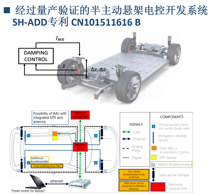
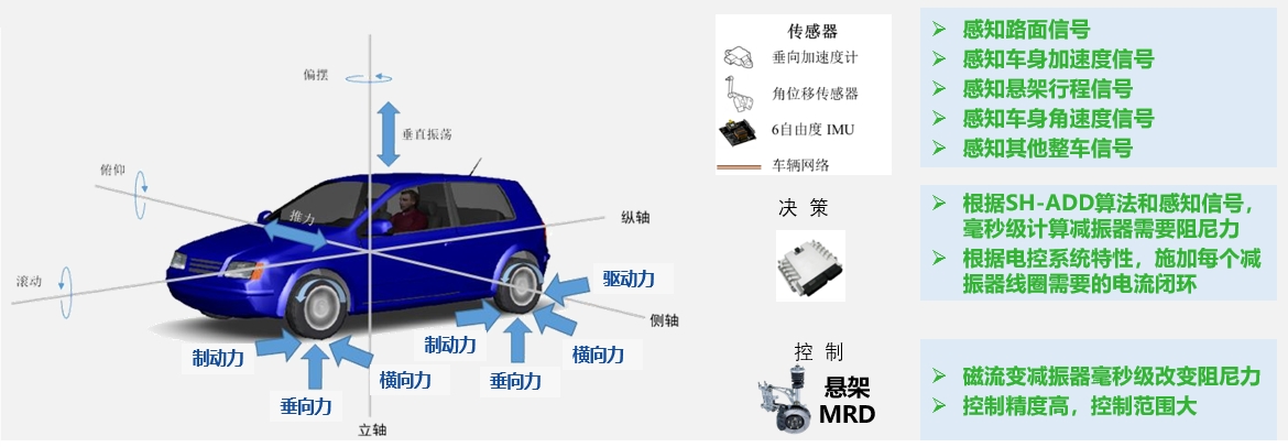
The magnetorheological intelligent suspension system developed and designed by Cosmartor International includes sensing system, intelligent control system, intelligent material (ie magnetorheological fluid) and magnetorheological damper.The perception system completes the information collection and uploading of the vehicle state, the intelligent control system completes the decision calculation and the application of the target current, and the magnetorheological shock absorber outputs the required target damping force to control the attitude of the vehicle.
Electronically Controlled Suspension: The Core of Vehicle Chassis Driving Experience Control
1) According to the basic principles of vehicle dynamics, the decisive factor for the overall attitude of the vehicle is the damping and stiffness of the suspension;
2) The electronically controlled suspension can independently adjust the damping and stiffness of the suspension, and can also coordinate other components (ESC, steering, ABS, etc.) to control other forces on the wheels;
3) The electronically controlled suspension can regulate the motion posture of the car to ensure the driving experience and driving safety of the vehicle, which is the key to the chassis-by-wire control.
Cosmartor International Intelligent Suspension fills the self-made commercial-grade magnetorheological fluid (MRF) in a specially designed magnetorheological damper (MRD). Each sensor is transmitted to the control system, and the controller calculates and makes decisions according to the preset control algorithm (optimized SH-ADD algorithm), issues corresponding commands, adjusts the current of the electromagnetic coils in each shock absorber in real time, and then changes the damping channel. The strength of the magnetic field produces different yield stresses and apparent viscosity coefficients, thereby adjusting the output damping force of the magnetorheological shock absorber, realizing the continuous and controllable adjustment of the damping force, and achieving the purpose of intelligent vibration reduction of the automobile suspension, thereby reducing the control of the automobile. Sex and comfort remain in perfect condition.
Intelligent Suspension System Architecture
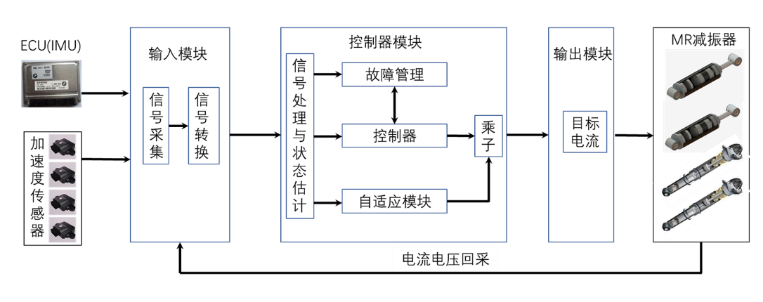
SAC Architecture Design Block Diagram
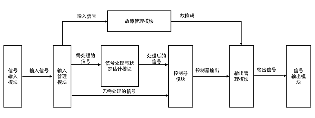
The SAC software is further divided into 7 sub-modules according to functions and objects: input, input management module, information processing and state estimation module, controller, fault management module, output management module, output, etc.
SAC function module
ID | Module | Function description |
1 | input | Receive vehicle CAN signals, collect sensor signals, IMU signals, and retrieve data such as ECU voltage and current. |
2 | input management | The input signal is normalized and normalized |
3 | Signal Processing and State Estimation | It includes three modules: filter, suspension sprung velocity and acceleration observer and suspension travel observer. The filter de-noises the input signal; the suspension sprung velocity and acceleration observer calculates and observes the suspension sprung vertical velocity according to the filtered roll angular velocity, pitch angular velocity, yaw angular velocity, and suspension sprung vertical acceleration. Velocity, suspension sprung vertical acceleration; according to the filtered sprung vertical acceleration and the observed vertical velocity, the observed stroke and the observed suspension relative velocity are calculated. |
4 | fault management | Fault identification and management of the electronically controlled suspension system; when a fault occurs, corresponding operations are performed according to the fault level and a fault code is issued. |
5 | controller | It includes SAC module, adaptive module, multiplier module and damping control module. The target current is calculated according to the observed and filtered sensor signal and CAN signal. |
6 | output management | The current signal in the form of an array is decomposed into the target currents corresponding to the four wheel direction shock absorbers; the faults diagnosed in the fault diagnosis module are summarized and output in this module. |
7 | output | The target current signal and fault information of the four shock absorbers in the output management module are transmitted to the bottom layer. The underlying driver receives the signal to drive the current loop to generate actual current and send out fault information. |
Control function description
|
ID |
Function |
Function description |
|
1 |
Adaptive control function |
|
|
2 |
sport mode |
Increase the damping force of the shock absorber to meet intense handling demands |
|
3 |
Comfort mode |
Soft damper characteristics to meet comfort needs |
|
4 |
driving mode selection system |
The characteristics of the shock absorber can be adjusted in a timely manner according to the information of different driving modes |
|
5 |
Bump&hole function |
Optimum comfort over speed bumps/buffers/manhole covers |
|
6 |
Anti-roll control function |
Change the damping force of the shock absorbers on the left and right sides to reduce the transient vehicle roll angle |
|
7 |
Anti-nodding control function |
The vehicle nodding is controlled by enhancing the damping force of the shock absorber by signals such as the brake pedal and the change in longitudinal acceleration, so that the front pitch of the body is small. |
|
8 |
Anti-backward control function |
The damping force of the shock absorber is appropriately increased in a short time by signals such as the brake pedal and the change in longitudinal acceleration to reduce the back-up during startup and sudden acceleration. |
|
9 |
Vehicle start/stop control |
Provide corresponding damping mode and control current according to vehicle start/stop control |
|
10 |
Output current closed loop monitoring |
Identify whether the output current reaches the expected value, and adjust if there is a deviation |


